is a compact, low mass unit giving smooth, non-vibrating power. Several types include vane, piston, percussion and turbine type. One of the applications include stirring of paint in a paint shop thereby avoiding the need to use electric motor in such hazardous explosive conditions.
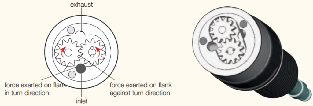
Tooth geared motor: Gear motors consist of two gear wheels, that run in a housing with minimal play. One gear-wheel is rigidly interconnected with the drift shaft, the other generates the torque. Two gear-flats are directed with compressed air into the turn-direction and one gear-flat against the turn-direction. The exhaust air is directed into chambers – that are formed between the gear-flat and housing wall – towards the exhaust air side and rotation is generated.
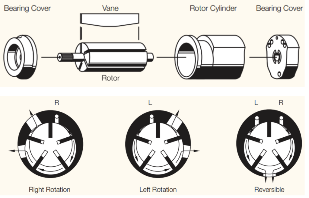
Vane Air Motor: Vane air motors are the most common type used in the process industry. It consists of a cylinder (a stator) and an enclosed rotor. The rotor is placed off-center, in an eccentric style, creating uneven space around the rotor. The vane-type structure divides the internal chamber into different areas of various sizes. These individual chambers, with uneven spacing between the rotor and stator, create a sealing mechanism.
The sealed chamber provides excellent conditions for exerting force by pneumatic air. The air passes from one chamber to another, creating a series of motions that result in continuous motor rotation in its respective direction.
Piston Air Motor: Piston air motors use multiple cylinders around a rotating shaft and can consist of up to 6 cylinders. Compressed air exerts a force on the cylinders, which rotates the shaft. Piston air motors are capable of delivering high torque at low speeds.
These are either radial or axial type as per arrangement of cylinders.
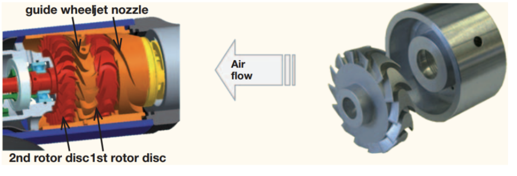
Turbine Air Motor: It uses a turbine wheel inside the motor. A rotor is attached to the turbine wheel, which consists of curved blades through which air passes. As the air passes, it turns the rotor, which rotates the motor. The conversion of the pressure energy into kinetic energy takes place in the inlet nozzle. On a two-stage turbine, the largest part of the kinetic energy is converted in the 1st turbine wheel. The air-flow is diverted over the stationary turbine wheel. The remaining energy is converted in the 2nd turbine wheel These air motors are used in applications that require high speed with low torque.
As compared to electric motors, they are compact in size, control of speed and torque is stepless, and are suitable for use in hazardous environments.
Selecting an Air Motor for the application:
Air vane motor is suitable for regular operating cycles.
Tooth-gear motors or turbines are more suitable for continuous operation (24 hour, non-stop).
Speeds:
Turbines and tooth-gear motors rotate in the upper speed range (up to 140,000 rpm). Air vane motors are available for very small speeds e. g. 16 rpm
Operation range:
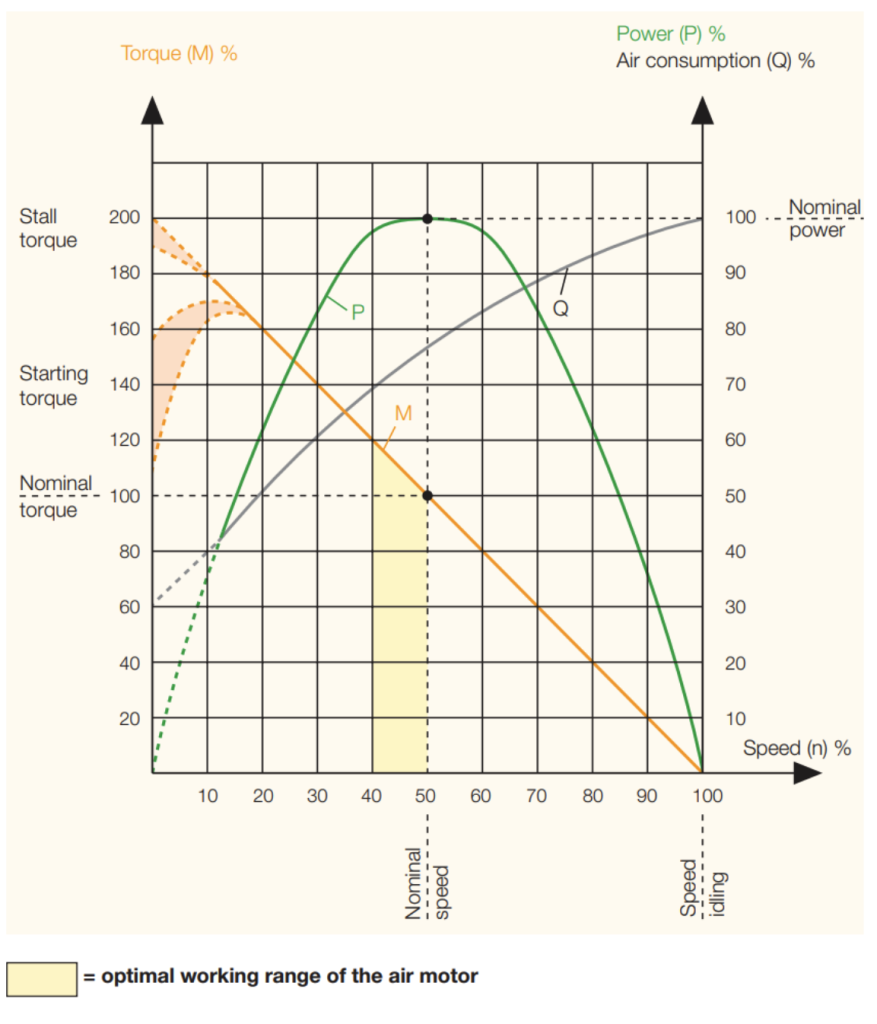
Air motors function in a very broad working range which can be decisively influenced by the amount of supplied air and the air pressure. Next determine the working position for your motor: Which nominal torque and which speed (when loaded) do you want to reach? The most economical operation of the air motor (least wear, least air consumption, etc.) is reached by running close to nominal speed. By torque of M = 0, the maximum speed (idle speed) reached. Shortly before standstill (n → 0), the air motor reaches its maximum torque (Mmax ≈ 2 x Mn). At nominal speed (nn), i. e. in the middle of the speed range, the air motor reaches its maximum power output (Pmax).
Performance curves for selection an air motor:
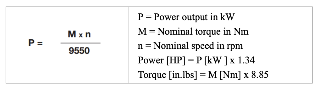
The correct calculation of the required drive is influenced by the required torque, the optimal working range of air motor, the necessary motor power and possibly any application conditions which affect performance.