In a variety of pneumatic applications the compressed air is exhausted to the atmosphere after completing the work or operation.
In pneumatic actuators, the piston is moved by compressed air and after completion of its movement the trapped air in the cylinder is exhausted through the port. This exhausted air can be reused by using combination of multi-port pneumatic valves and accumulators.
There are two approaches to recycle the exhaust air: (1) adding an air storage device in the exhaust circuit as a supplementary air source, and (2) adding a by-pass valve to directly use the exhaust air. A method is devised to store part of the high pressure air on the exhaust side in a container during the exhaust process.
When the actuator moves in the opposite direction, this part of the air would enter the charging side as pressurized air, thereby saving energy.
Adding a pneumatic accumulator is another approach to recycle the air exhausted by the pneumatic system.
Below diagram shows, the piston movements (an advance and a return) for each cylinder in the system configuration.

The indicative energy-saving circuit with a pneumatic energy accumulator and the circuit schematic diagram is shown as below:
It is mainly composed of a supply air source, pressure reducing valve, quick exhaust valve, two throttle valves, a flow sensor, two three-position five-way solenoid valves, two cylinders, a pressure sensor, and a pneumatic strain energy accumulator. The function of the throttle valve 1 is to adjust the air flow into the system. Flow sensor four is used to collect the airflow into the system, the throttle valve seven is used to adjust the airflow into and out of the device, the quick exhaust valve is used to discharge the residual air of the pneumatic strain energy accumulator, and pressure sensor nine is used to monitor the air pressure in and out of the accumulator. Accumulator ten is used to recover the exhausted air discharged from cylinder 4 and supply it to cylinder 10.
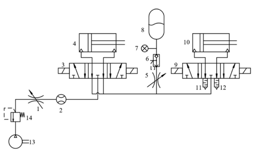
Pneumatic energy-saving circuit with pneumatic strain energy accumulator.
1—Throttle valve,
2—Flow sensor,
3—Three position five-way solenoid valve,
4—Primary cylinder,
5—Throttle valve,
6—Quick exhaust valve,
7—Pressure sensor,
8—Accumulator,
9—Three position five-way solenoid valve,
10—Secondary cylinder,
11, 12—Muffler,
13—Air compressor,
14—Pressure reducing valve.
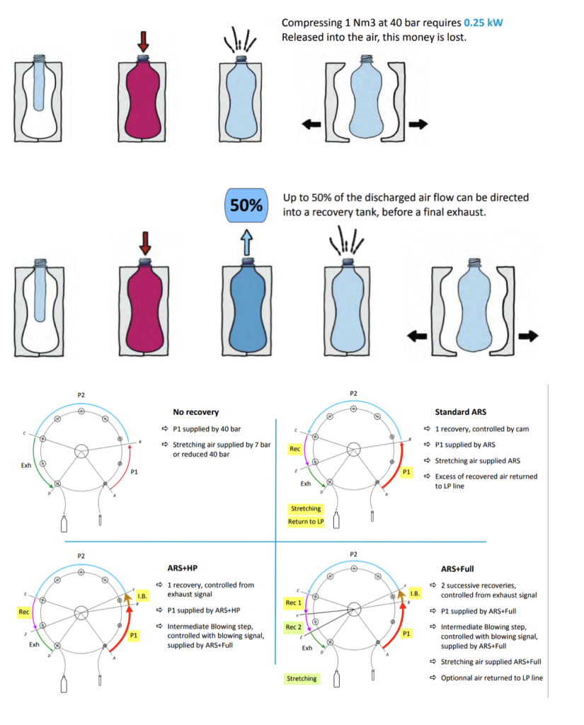
Whereas, inPET bottle blow moulding operations both high-pressure and low-pressure compressed air is used. Exhausting of all residual compressed air from the high-pressure side out into the atmosphere was probably considered unavoidable and not especially wasteful in earlier times.
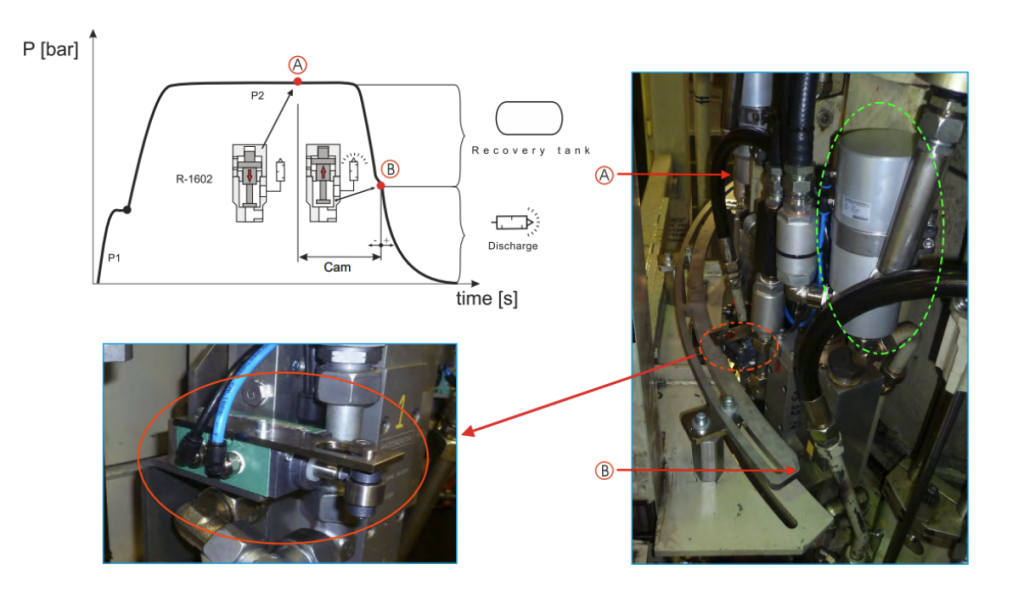
Air Recovery system (ARS) recovers spent air from the polymer bottle-blowing process and uses it for the initial blow on preforms or feeds it into the plant compressed air distribution system.
The blow moulding process requires ultra-high air pressure, in excess of 580 psig (40 barg), for the bottle-blowing process. The ARS recovers compressed air after the bottle forming process at a residual pressure of 140 to 150 psig (9.5 to 10 barg). The recovered air can be used for the preform blow or can be tied into the plant’s low-pressure compressed air distribution system for use anywhere in the facility.
Following is an illustration of recovering of compressed air blown in 40 barg PET moulding operation.